When installing a second Chemistry Board with one already installed.
Click here for a downloadable version.
Prior to installation, be sure to have the following ready:
- The Dual Body of Water Chemistry Board itself
- 2 – M3 mounting screws (included with the Dual Body of Water Chemistry kit)
- 2 – board standoff screws (included with the Dual Body of Water Chemistry kit)
- The 2-wire communication cable to connect the board to the main board of The Attendant (included with the Dual Body of Water Chemistry kit)
- #2 Phillips/crosshead screwdriver
- Small adjustable wrench or 5mm socket wrench
- Small needle-nose pliers

Wiring Installation
Remove the bottom cover of The Attendant.
You can do this by loosening each of the 5 crosshead screws on it, then lifting it up and out. Please note the screws do not come out and will remain attached to the cover.

Loosen the mounting screws on the top cover and lower it down from the top.

Route the 2-wire communication cable
Route the 2-wire communication cable from the area where the currently installed Chemistry Board is, up and under the top cover, between the center pillar and the transformer. See the following for guidance:

The 2-wire cable should be fed down below towards the GPIO2 connector.

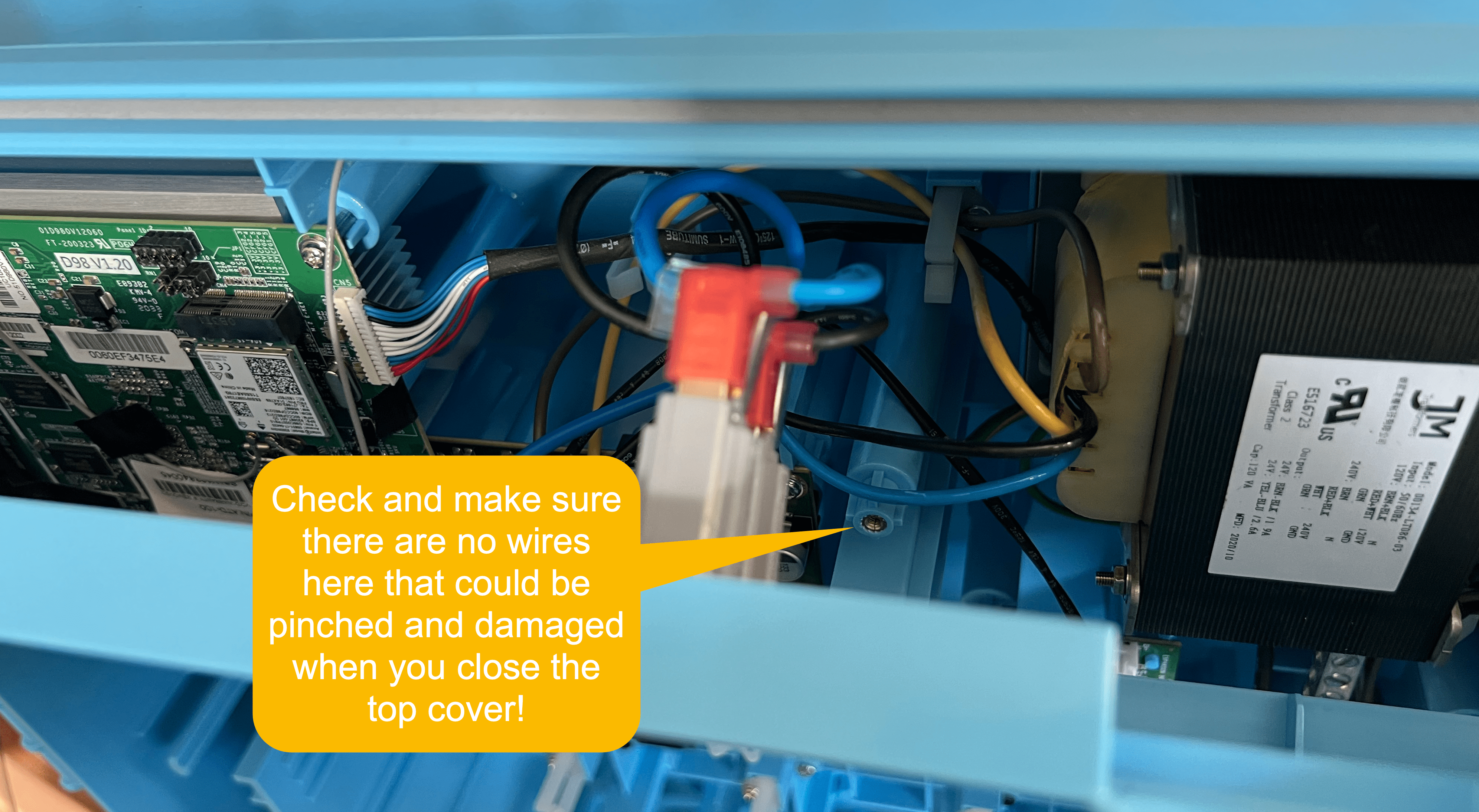
Close up the top portion of The Attendant
Close up the top portion of The Attendant and fasten it down. When swinging the top cover back into place, be sure to avoid pinching wires between the cover and the center pillar. See the following.
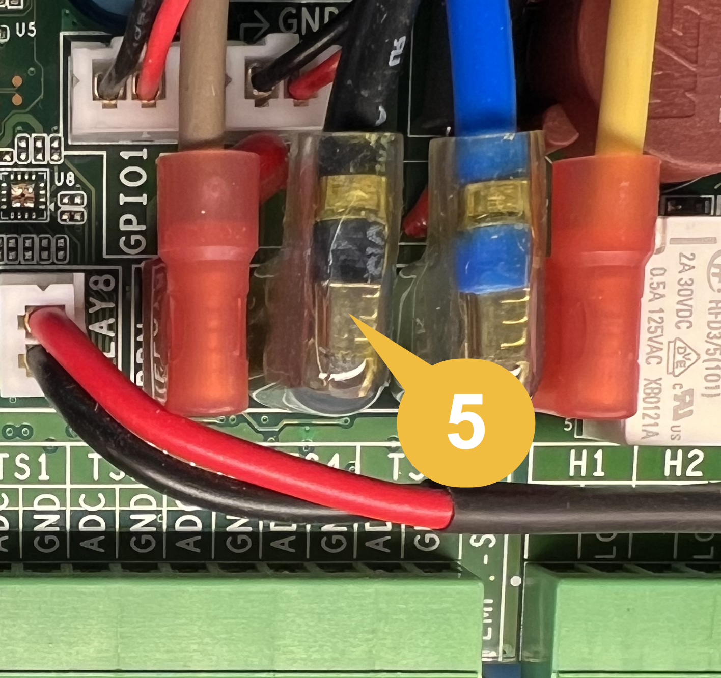
Connect the 2-wire communication cable to the GPIO2 connector
The GPIO2 connector is situated behind some blade spade connectors. It might be necessary to disconnect a couple of the spades so that you can easily connect the 2-wire communication cable to the GPIO2 connector. You can use a small set of needle-nose pliers to pull out the connector if needed.

Once you have the connection made, reattach the blade connectors (which provide electrical power to The Attendant).

Dual Body of Water Chemistry Board Installation
Prepare the currently installed Chemistry board
Next, you will need to remove the two crosshead screws that are currently installed on the first Chemistry board – the “bottom” one.
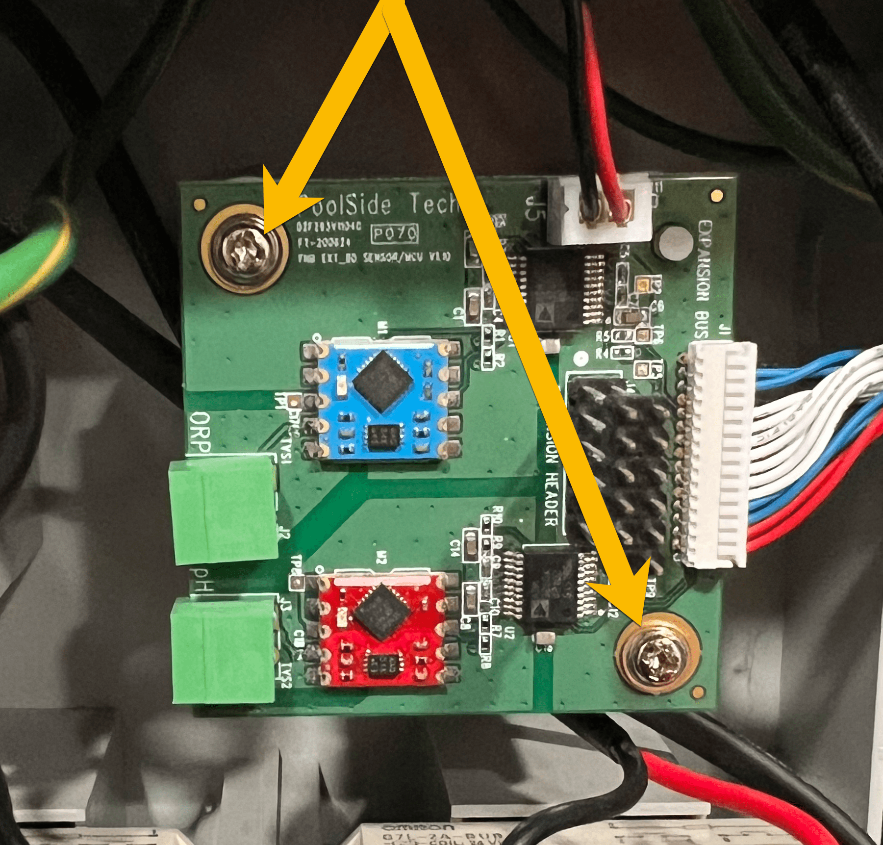
Install the 2 standoff screws
Use the 2 standoff screws to replace the crosshead screws on the bottom board by holding it in place while hand-tightening them in. Use a small wrench or 5mm socket to gently tighten each standoff. Do not over-tighten!
Connect both boards using the 10-pin expansion connector
Align the 10-pin expansion connector from the bottom board with the 10-pin socket on the underside of the Dual Body of Water Chemistry board and connect the 2 boards together on top of one another.

Gently push down on the top board so that the holes from the standoffs are right below the top board mounting holes. Do not use excessive force or else you could damage the connectors and possibly both Chemistry boards.

Secure the Dual Body of Water Chemistry board
Use the 2 M3 crosshead screws provided with the Dual Body of Water Chemistry kit to finish mounting the top board. Tighten gently – do not use excessive force.
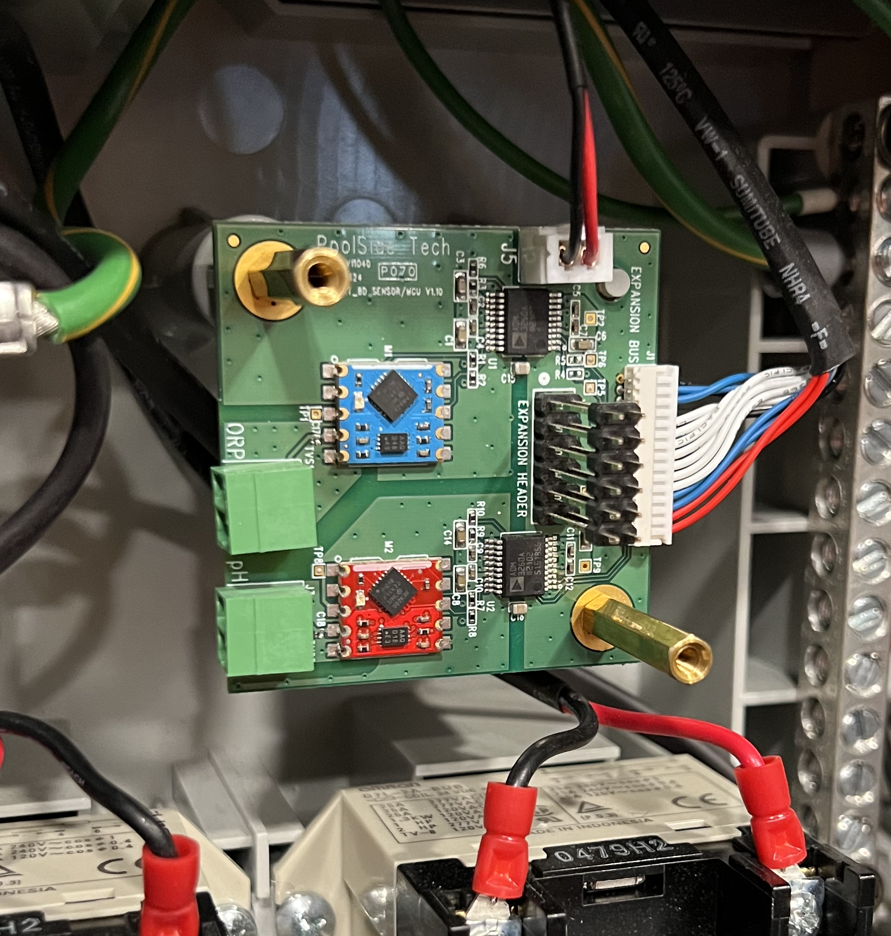
Now that the top Dual Body of Water Chemistry board is installed, carefully connect the 2-wire communication cable into the J5 connector as shown below.

Double Checking Your Work
Re-check the following before moving on.
- The 2-wire communication cable has been connected from GPIO2 to the J5 connector on the top Chemistry board.
- The bottom Chemistry board still has its own 2-wire communication cable still connected.
- The bottom Chemistry board still has its own 15-pin ribbon wire/connector attached.
- The top Chemistry board does NOT have a 15-pin ribbon wire/connector connected.
- Any temporarily disconnected blade/spade connectors have been reattached.