Connecting and configuring your PAL drivers and lights to The Attendant is simple. Once you’ve completed the physical wiring from the lights to the driver you’ll need to set the DIP switches correctly and input the proper addresses into The Attendant’s software.
Only PAL Driver models #PCR-2DMX and #PCR-3DMX are compatible with The Attendant for DMX control. Non-DMX models must be set to Pentair, Hayward, or Jandy mode and configured accordingly in the app.
Click here to see PAL Driver Models
Communication Wiring
PAL Drivers should be wired directly from the power supply and should not be routed though a relay. The Attendant requires constant power to the PAL Driver for communication.
When wiring a single PAL driver, connect the + and – terminals from the “DMX In” on the driver to the D+ and D- terminals of a BUS port on The Attendant.

DIP Switch Settings
Each light Zone wired to your PAL drivers must be configured as a light device on The Attendant. Every zone has its own set of addresses for red, green, and blue, which The Attendant uses to control the colors and lighting effects available to you.
Addresses are derived from the combination of the DIP switch settings within each PAL driver.
PCR-2DMX (Old Style)
For the PAL model PCR-2DMX driver, there are two switch banks (Module Config and Other Config) that set the addresses for the two zones supported by this driver. Dip switch positions UP is ON and DOWN is OFF.

Refer to the sheet below to adjust the DIP switches for your desired control zones. Click the spreadsheet to enlarge.

PCR-3DMX
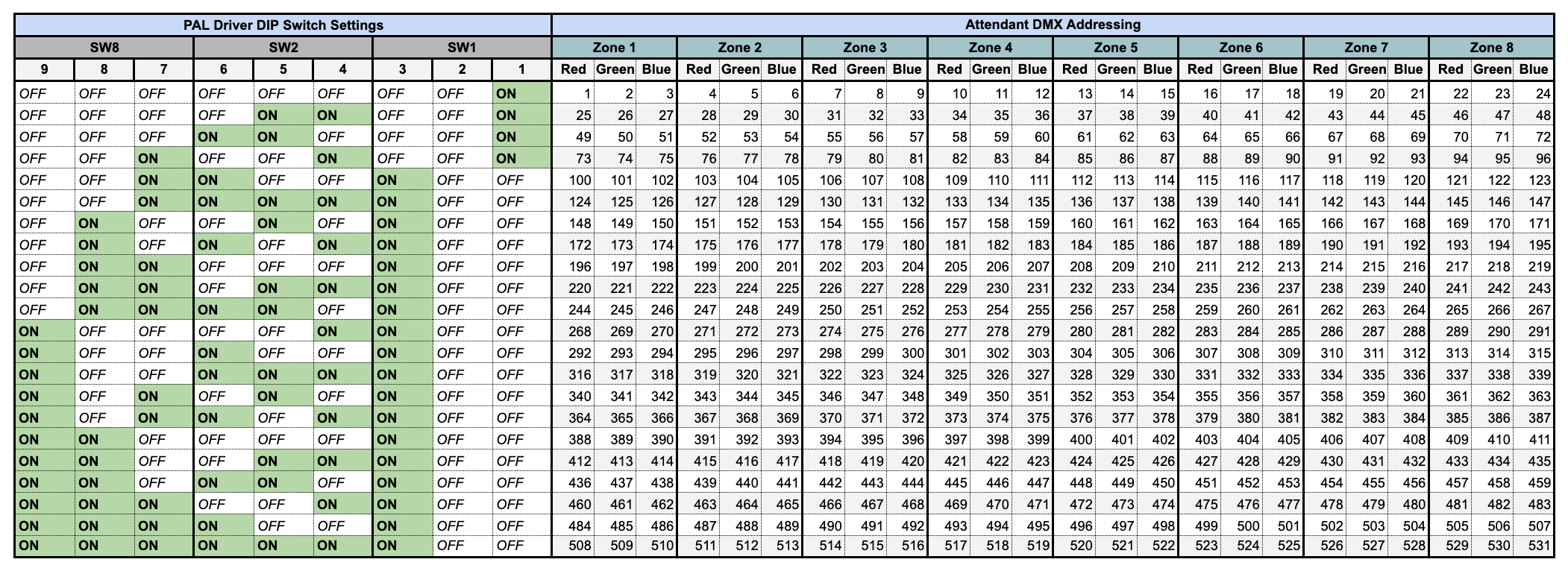
For the PAL model PCR-3DMX driver, DIP switches 9-1 determine the addresses for the 8 supported zones. The location of these switches is shown in the image below. Dip switch positions: DOWN is ON and UP is OFF.

Refer to the sheet below to adjust the DIP switches for your desired control zones. Click the spreadsheet to enlarge.
PCR-2DMX V3
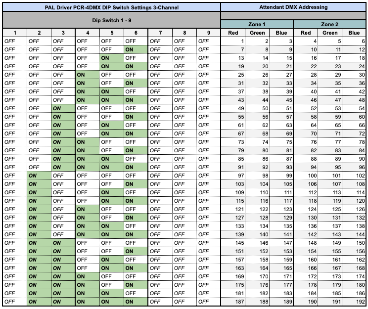
For the PAL model PCR-2DMX driver, DIP switches 1-9 determine the addresses for the 2 supported zones. The location of these switches is shown in the image below. Dip switch positions: DOWN is OFF and UP is ON.

Refer to the sheet below to adjust the DIP switches for your desired control zones. Click the spreadsheet to enlarge.
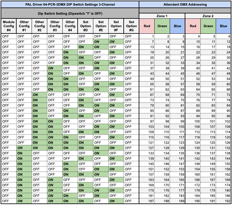
64-PCR-3DMX V3 (3-Channel – Red, Green, Blue)
The PAL PCR-3DMX driver uses DIP switches to assign DMX addresses for the two supported zones. The DIP switch bank is shown in the image below and is outlined in orange.
When configuring DIP switches, DOWN indicates OFF and UP indicates ON.
- DIP Switch A (outlined in red) must be set to ON for proper operation.
- The DMX termination shunt (outlined in blue) must be installed over the E pin to enable DMX communication.
Note: If the termination shunt is not installed on the E pin, the driver will not respond to DMX commands.

Refer to the sheet below to adjust the DIP switches for your desired control zones. Click the spreadsheet to enlarge.
64-PCR-3DMX V3 (4-Channel – Red, Green, Blue, White)
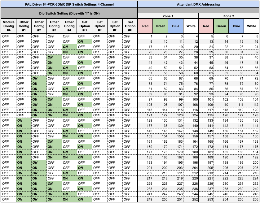
When using the 4 Channel Mode, select Brand (Generic) and Expected Colors and Shows as (DMX – RGBW)
Basic Configuration Example
For many installations, there will be one PAL driver installed, controlling two zones – usually the pool and spa.
Referencing our tables, you’ll find the Red/Green/Blue addresses for each zone, and depending on the model of your driver, you’ll need to use the values for either v1 or v2 of the schema.
As v2 is the most recent update from PAL Lighting, we will assume we have the latest model driver, so we will use addresses 1 through 6 to setup the lights in the app.
When you create a new light device in the mobile app, you will need to configure it as follows:
- Brand: PAL
- Expected Colors and Shows: DMX
- Off/On Timing: DMX
The Port Type will be BUS. The Port Number is the BUS port on The Attendant that you’ve wired the driver to.
The Address Mapping section is where the addresses get input.
For the first zone, input 1 in the Red field, 2 in the Green field, and 3 in the Blue.
When creating the second light for the second zone, you would enter 4 for Red, 5 for Green, and 6 for Blue.

Advanced Configurations Using More than One PAL Driver in Series
When you have more than one driver wired to provide lighting to additional zones, you will need to tie each driver together using the provided In and Thru terminals on the communications board.

From driver 1, wire D+, D-, and Shield from the Thru output and connect those to the In input on driver 2.

Remove the Thru terminator jumper from driver 1. Keep it on driver 2 unless you’re adding another driver after that.
Set the address for driver 2’s first zone by entering 7 in the Red field, 8 in the Green field, and 9 in the Blue.
For the second zone, use 10 for Red, 11 for Green, and 12 for Blue.
Make sure driver 2 has different DIP switch settings than driver 1 to ensure independent control of all zones.
Troubleshooting
Signal LED:
When in DMX mode, the “CPU” LED on the PCB acts as a DMX signal indicator. This LED lights up during DMX packet transmission, and its flash rate depends on the DMX controller in use. At high refresh rates, the signal LED may appear to remain solid.
Loss of DMX:
If the DMX signal is lost, the output levels are maintained for 60 seconds before being turned off. After an additional 60 seconds without DMX, the fan (if installed) will also shut off.
No DMX Signal:
- Check and ensure connections via the green BUS terminals.
- Verify that the same wires are connected in the same positions (e.g., blue is positive on both the driver and the DMX transmitter).
- Ensure the DMX transmitter has power.
- Confirm the DMX controller is programmed for the correct channels.
DMX Signal but No Lights:
- Verify the starting channel in your DMX controller is correct.
- Ensure the DIP switches match the intended configuration.
Colors are Incorrect:
- Check the coding in the DMX controller and confirm no numbers were skipped in the driver programming.
Other:
The software includes temperature limiting. If the temperature exceeds approximately 60°C, output levels will be reduced to prevent overheating.