Free and total chlorine probes are sensors that provide continuous, in-line measurement of chlorine levels for precise water chemistry control. Designed for direct integration with The Attendant, these probes deliver real-time data to support automated dosing and ensure compliance with water quality standards. Proper installation, calibration, and maintenance are essential for accurate readings and long-term probe performance.
Probe Assembly
Before using the Chlorine Probe, you’ll need to fill the membrane cap with Internal Filled Gel (IFG). Follow the step-by-step instructions (Steps 1–8) provided below to complete the assembly.
Important Notes:
- Make sure the electrode is powered off during assembly.
- Always wear safety glasses and gloves during handling.

Step 1: Required Components
Before beginning assembly, make sure you have all necessary components:
- Internal Filled Gel (IFG)
- Electrode and membrane cap
- Protective boot (for storage and transport)
- Electrode polishing strips
Step 2: Remove Protective Boot
Carefully remove the protective boot from the electrode or membrane cap before proceeding with assembly.

Step 3: Prepare the Membrane Cap
- Unscrew the membrane cap from the electrode.

- Gently lift the silicone band to uncover the vent hole. Make sure the vent hole is exposed to air.

- Do not use sharp tools during this step.
- Set the membrane cap aside for now.
Note: Be careful not to touch or damage the gray area on the electrode. This is the Silver Halide Coating, which is essential for proper sensor function.
Step 4: Polish the Working Electrode Tip
- If the probe is not new, polish the dry gold tip of the Working Electrode (WE) using the provided polishing strip.
- Polish in one direction only, just enough to make the tip shiny.

- A few gentle strokes are sufficient — do not over-polish.
- Avoid touching the gray Silver Halide Coating during this process.
- Once polished, rinse the electrode with deionized (DI) water.
Note: New probes do not require polishing before use.
Step 5: Fill the Membrane Cap with Internal Filled Gel (IFG) WEAR GLOVES
- Carefully fill the membrane cap with IFG up to the upper threads.
- Do not shake the IFG bottle before use.

- Slowly dispense the IFG along the inner sidewall to minimize the risk of trapping air bubbles.
- Ensure that no air bubbles form in the center hole (white area inside the cap).
- Remove any water droplets from the center hole before filling.
Note: If a large air bubble appears near the white membrane, either use a syringe to remove it or discard the IFG and try again with a fresh fill.
Step 6: Attach the Membrane Cap WEAR GLOVES
- Ensure the silicone band is not covering the vent hole before installing the membrane cap.
- Carefully screw the membrane cap onto the electrode until it is finger-tight.
- The exposed vent hole will allow any excess IFG to escape during installation.
Note: Perform this step over a sink with running water to rinse away any IFG that may overflow during the process.
Step 7: Seal and Rinse
- Gently press the silicone band back into the recessed groove to seal the vent hole.
- Rinse the entire electrode thoroughly with clean water to remove any remaining IFG before use.
Step 8: Final Prep
- Gently wipe off any excess water from the electrode using a clean, soft cloth.
- The electrode is now ready for installation, wiring, and initial conditioning.
Notes:
- Avoid touching the center membrane—keep it free from dirt, sharp objects, or anything that could damage it.
- Seal the IFG bottle immediately after use to prevent the remaining IFG from drying out.
Installation of the Flow Cell
The chlorine probes must be installed in a dedicated flow cell to ensure stable, accurate readings. Use the ATT-CHLOR-FLOW-CELL and ATT-CHLOR-FLOW-REG components as outlined below.
Required Components
- ATT-CHLOR-FLOW-CELL – Probe housing
- 1 FLOW-CELL Required per probe
- ATT-CHLOR-FLOW-REG – Adjustable flow regulator (Only 1 Required)
Installation Instructions
1. Choose an Installation Location
- Install the flow cell after the filter and before any chemical injection point.
- The flow cell should be mounted vertically on a wall or backboard.
2. Mount the Flow Cell
- Secure the ATT-CHLOR-FLOW-CELL to a stable surface using appropriate fasteners.
- Keep the chamber upright so air bubbles rise away from the sensor.

3. Connect Plumbing
- Install a dedicated sample line from the main return line after the filter to the inlet of the ATT-CHLOR-FLOW-CELL. This ensures only filtered water enters the flow cell.
- Connect the outlet of the Flow Cell to the inlet of the Flow Regulator (FLOW-REG).
- From the outlet of the FLOW-REG, route the water back to the system by connecting to either:
- A low-pressure return line (typically located after all pool equipment), or
- A dedicated return path suitable for returning low-flow water to the pool.
Use tubing or rigid PVC that is chemically compatible with pool water. Ensure all plumbing is secure and leak-free.
4. Insert the Probe
- Carefully install the CHLOR-PROBE into the FLOW-CELL.
- Hand-tighten only. Do not overtighten, as this may damage the probe or O-rings.
- Confirm that the stainless-steel ring is fully submerged in water.
5. Adjust Flow Rate
- Open the sample valve and slowly adjust the flow regulator until the flow is steady (recommended 30–65 l/h).

- Avoid turbulent or high-velocity flow inside the probe chamber.
- Ensure no air bubbles are present in the flow cell.
Wiring the CHLOR-PROBE to The Attendant
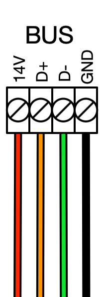
The ATT-FREECHLOR-PROBE and ATT-TOTALCHLOR-PROBE communicate via RS485 and should be connected to any available BUS port on The Attendant.
Note: These probes do not require a Chemistry Board and should not be connected to one.
Before You Begin
- Power off The Attendant controller before making any wiring connections.
- Identify an open BUS port on The Attendant.
- Follow the diagram to the right for proper wiring.

Programming the Probe in The Attendant
Enter Installer Mode
- Open The Attendant app and tap the hamburger menu (☰).
- Go to Maintenance and select Installer Mode.
- Choose your entry method and tap Enter Installer Mode.
Add Chlorine Probes
- In Installer Mode, tap Devices.
- Use the + button to add a new device.
- Select Chlorine Sensor from the list.
- Select Model type, then Port Type and Number.
- Tap APPLY , then tap SAVE.


Assign Probes to a Flow
- Go to the Flows tab.
- Choose the flow where your probe is installed.
- Tap Edit, then use the + icon at the sensor location.
- Select your Chlorine probe devices.
- Tap APPLY, then SAVE to confirm.
Do Not Exit Installer Mode > Go to next section > Probe Calibration
Chlorine Probe Calibration
Before calibration of any Chlorine Probe, be sure that the Cyanuric Acid(Chlorine Stabilizer) in the pool is already to its optimal level or recalibration of the Chlorine Probe will be required.
- From Installer Mode in the App, turn on the pump that supplies flow to the Chlorine Probe
- Tap > on the Chlorine Probe then select Calibrate to start the Calibration Wizard

- The system will attempt to turn on the probe
- You will now be prompted with a message: Before calibration, ensure the following is completed
- The probe is properly assembled with Internal Filled Gel and a membrane cap.
- The probe is installed in a flow cell with flow between (8-16 GPH or 0.13-0.26 GPM)
- The stainless steel counter electrode is fully submerged in water.
- The probe is connected to The Attendant.
5. Now you can select Calibration – Recommended

6. Now the Conditioning process will begin
- This process will take between 1 to 4 hours.
- Do NOT disconnect the probe during this process.
- Keep the system in installer mode and do not exit installer mode until this process is complete.
7. When the Conditioning process is complete, the Calibrate button will highlight blue at the bottom of the screen and you can now tap it.
8. Calibration is now complete.
The Chlorine Probe is now ready to use and you can exit installer mode.
Setting Chlorine Setpoints in the App
- From the Home Screen of The Attendant app, tap the chemical beaker icon next to the body of water status bar.
- In the Chemistry Settings, select the Sanitization tab at the top.
- Ensure Sanitizer Type is set to Free Chlorine or Total Chlorine.
- Set your desired Chlorine Target (ORP setpoint), such as 3.0.
- Use the toggle to enable or disable alerts for Sanitization.
- Set the Notification Delay — the time the system waits after detecting an out-of-range ORP before sending an alert.
- Configure Sanitization Alert Thresholds:
- Set the value for low chlorine alerts.
- Set the value for high chlorine alerts.
- Set the value for low chlorine alerts.
- If applicable, tap the Sanitizer button (e.g., Salt) at the bottom to access chlorine dosing settings.
Electrode Maintenance Overview
Proper maintenance of the chlorine probe ensures accurate readings and long-term reliability. Depending on your water chemistry, bather load, and overall system conditions, regular maintenance may include re-gelling the sensor, cleaning or replacing the membrane cap, polishing the gold tip, and storing the probe correctly during downtime.
Replacing the Internal Filled Gel (IFG)
The IFG inside the probe should be replaced approximately every 3 months. You should also consider replacing it if:
- The stainless steel ring (counter electrode) was exposed to air for more than 5 minutes while powered on.
- The probe starts reacting to monochloramine or gives inconsistent readings.
- The pH sensitivity changes by more than 15% per pH unit.
- You’ve recently cleaned or replaced the membrane cap, or polished the gold electrode.
Replacement Steps:
- Power off the system and disconnect the probe from the controller.
- Slide the rubber vent band down toward the bottom of the membrane cap.
- Unscrew the membrane cap and remove any remaining IFG from inside the cap or probe body.
- Rinse both the cap and the internal sensor body with tap water, then with distilled water.
- Refill the cap with fresh IFG and reinstall it (refer to Electrode Assembly, page 3, steps 5–8).
Cleaning the Membrane Cap (Descaling)
In pools with high hardness levels, scale buildup (white or green deposits) can block the membrane and reduce probe performance. If the slope is low and visible scale is present, descaling is recommended.
Descaling Instructions:
- Power off and remove the probe from the water.
- Slide the rubber band down and remove the membrane cap.
- Clean out old IFG and rinse with water (tap, then distilled).
- Protect the gold and silver elements from direct sunlight during cleaning.
- Prepare ~150 mL of 0.1N sulfuric acid (or hydrochloric acid) in a small beaker.
- Add 3–4 drops of fresh bleach, mix thoroughly.
- Soak the membrane cap for 1–4 hours or until the visible scale is gone.
- Rinse thoroughly with DI water, blot dry, refill with IFG, and reinstall the cap.
Replacing the Membrane Cap
Replace the membrane cap if:
- It’s physically damaged or cracked
- Probe readings are unstable or slow to respond
- Linearity is poor even after cleaning
- The slope drops below 20% of expected value
Replacement Instructions:
- Power down and disconnect the probe.
- Slide the vent band down and unscrew the old membrane cap.
- Discard the old cap and unpack the new one on a clean surface.
- Rinse the new cap with clean water, then rinse with a small amount of IFG.
- Fill with fresh IFG and reinstall per Electrode Assembly (page 3, steps 5–8).
Polishing the Gold Working Electrode (WE)
If the zero offset is outside the 0 ±100 mV range or the probe fails to stabilize, polish the gold WE to remove surface buildup.
Polishing Steps:
- Power off and remove the probe from the water.
- Remove the membrane cap.
- Using a polishing strip, gently polish the gold tip in a single direction until it looks shiny and clean.
- Avoid over-polishing and do not touch the silver halide coating.
- Rinse the tip with clean water, then refill the cap with IFG and reassemble.
Proper Storage
If the probe won’t be used for a while, store it correctly to extend its life:
- Short-term (under 1 week): Leave IFG in the cap and soak just the cap in clean water.
- Mid-term (1 week to 1 month): Leave IFG in the cap, but store dry in a clean, shaded location.
- Long-term (over 1 month): Remove the IFG and store dry with the tip protected.
Important: The reference (silver) electrode is sensitive to light—keep it capped and out of direct sunlight when not in use.
Effect of Cyanuric Acid on Chlorine Probes
CYA is used as a chlorine stabilizer in pools/spas to protect against chlorine breakdown from sunlight. The typical effect of CYA usually depends on the FC/CYA ratios, as shown in the graph below. The results were obtained by gradual addition of CYA at the free chlorine (FC) concentrations noted in the graph.

It is notable that the addition of CYA causes an obvious decrease in the electrode output when the concentration of CYA is less than 10 ppm, while CYA > 10 ppm, its effect on the probe is almost constant.