
The Attendant supports pressure monitoring using Poolside Tech pressure sensors. Pressure sensors can be used to monitor system pressure and provide real-time pressure information directly through The Attendant.
Two pressure sensor models are available:
- RS-485 Pressure Sensor
- 4–20 mA Pressure Sensor (Requires Chemistry Board)
Wiring the Pressure Sensors
RS-485 Pressure Sensor
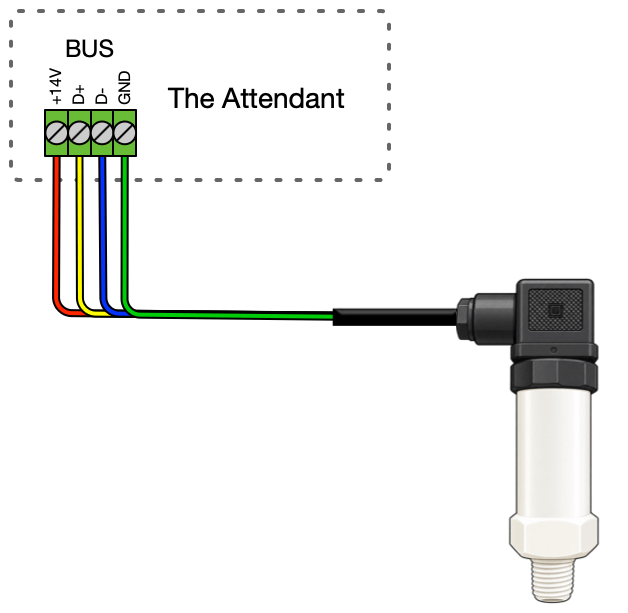
The RS-485 pressure sensor connects to an available BUS port on The Attendant.
Wire the pressure sensor as follows:
| Wire Color | Attendant BUS Connection |
|---|---|
| Red | +14V |
| Yellow | D+ |
| Blue | D- |
| Green | GND |
4-20mA Pressure Sensor
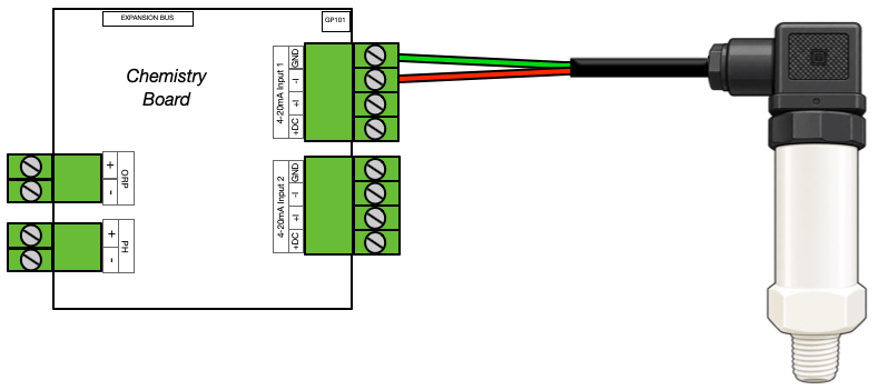
The 4-20mA pressure sensor connects to an available chem board input on The Attendant.
Wire the pressure sensor as follows:
| Wire Color | Attendant Chemistry Board 4-20mA Connection |
| Red | -I |
| Green | GND |
Installing the Pressure Sensor
The Poolside Tech pressure sensor uses a 1/4″ NPT connection and can be installed in several locations on the pressure side of the circulation system.
The installation location should be selected based on the equipment layout and the pressure point you want to monitor.
Option 1: Pump Pressure-Side Freeze Plug
The pressure sensor can be installed directly into the pressure-side freeze plug location on the pump, when the pump has a compatible threaded port.
Remove the pressure-side freeze plug and install the pressure sensor into the available port.
This provides a direct measurement of pressure at the pump discharge and is typically the simplest installation when a compatible port is available.
Important: Make sure the sensor is installed on the pressure/discharge side of the pump, not the suction side.
Option 2: Tee Between the Pump and Filter
The pressure sensor can also be installed in the plumbing between the pump discharge and filter inlet.
Install a tee with a 1/4″ NPT threaded connection and install the pressure sensor into the tee.
This is a good option when the pump does not have an available pressure-side port or when a dedicated sensor location is preferred.
Option 3: Filter Installation
The pressure sensor can be installed at the filter using a brass tee.
Install the brass tee at the filter’s existing pressure gauge connection, then reinstall the existing pressure gauge into one side of the tee and install the Poolside Tech pressure sensor into the other.
This allows the existing mechanical pressure gauge and The Attendant pressure sensor to be used at the same location.
Installation Notes
Before installing the pressure sensor:
- Turn off the circulation pump.
- Relieve all pressure from the filtration system.
- Verify the installation location is on the pressure side of the circulation system.
- Use only Teflon Tape, do not use paste for the sensor.
- Do not overtighten the pressure sensor.
- Position and route the sensor cable so it is protected from damage and does not place unnecessary strain on the sensor connection.
WARNING: Never remove a pump plug, filter pressure gauge, or other pressure-side fitting while the circulation system is running or while the system is under pressure.
Programming the Pressure Sensor
Once the pressure sensor has been installed and wired, it must be added to The Attendant and assigned to the appropriate flow.
Adding the Pressure Sensor
- Enter Installer Mode.
- Navigate to the Devices menu.
- Tap the + button to add a new device.
- Select Pressure Sensor.
- Select the pressure sensor model being installed:
- RS-485 Pressure Sensor
- 4-20mA Pressure Sensor
RS-485 Pressure Sensor
When adding the RS-485 model, select the BUS port where the pressure sensor is wired.
Verify the settings, then tap Apply and Save.
4-20mA Pressure Sensor
When adding the 4-20mA model, select the chem board input where the pressure sensor is wired.
Verify the settings, then tap Apply and Save.
Adding the Pressure Sensor to a Flow
After the pressure sensor has been added as a device, it must be placed in the flow where it is physically installed.
- Navigate to the Flows tab.
- Select Edit on the flow where the pressure sensor is installed.
- Tap the blue + at the location in the flow that represents the physical location of the pressure sensor.
- Select Pressure Sensor.
- Select the pressure sensor that was just added.
- Verify that the pressure sensor is shown in the correct location within the flow.
- Tap Apply, then Save.
The pressure sensor should now display the measured system pressure within The Attendant.
Setting up Pressure Alerts
COMING SOON!