Disconnect the Pump Display/Controller
Before attempting to wire the pump to The Attendant, you’ll need to remove the Local Controller display (JEP-R or iQPUMP01) following the instructions in the pump manual.
- Remove power from the pump by disconnecting the high voltage lines or by turning off or deactivating any breaker to which the pump power is connected.
- Lift up the controller cover on its hinges to access the variable-speed controller.
- Remove the six (6) screws to disconnect the variable-speed controller from the controller base on the pump motor.
- Detach the RS-485 cable connecting the variable-speed controller user interface to the controller base on the motor. Do not over extend the cable when raising the controller away from the motor.
- Unscrew the four (4) connector terminals and disconnect the wires of the motor cable assembly. Note: Do not cut the cable, or you will lose the ability to return to the default factory configuration.
- Bundle the loose wire into the pocket of the controller base. This wire will be used if reinstalling the variable-speed controller onto the pump later if needed.
- Secure the pocket cover and gasket with six (6) screws to the variable-speed controller base on the motor.
Serial RS-485 Connection for Variable Speed Control (Recommended)
In order to connect the VSFloPro to The Attendant controller wires from pin 2 and 3 (black and yellow) from the pump connector must be wired to the D+ and D- lines on one of the four communication bus terminals on The Attendant controller (labeled BUS1 through BUS4).
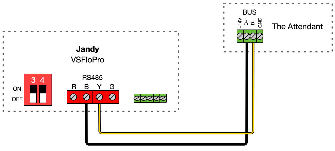
You will also need to ensure the DIP switches are set correctly so that they can be operated by The Attendant. Switches 1 and 2 should be set to the OFF position, and 5 should be left ON. Switches 3 and 4 define the pump “bus identifier” that will be used in the Poolside configuration. Use the following chart to find or set the right value.

Low Voltage/Dry Contact Connection
Utilizing four of the dry contact relays (Heater ports) on The Attendant PCB, labeled H1 through H5, the VSFloPro can be set to one of four predefined speeds. This mode does not allow precise control over pump RPM speed and may limit the energy savings seen from using The Attendant controller.
The speeds that are achieved are listed in the following table:

Wiring diagram for Jandy VSFloPro dry contacts:
